from Rob Legg Yachts | |||||
|
|
|
|
|||
Part 1The ideal sailing boat will never exist!Every thing to do with a sailing boat is a compromise. The wind and the sea are never the same from day to day. One day you may want to go for a sail on your own, the next several friends would be good company, and come the weekend there is a race at the local club. Some decisions must be made!
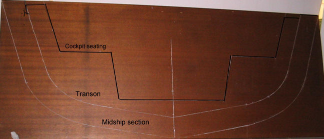
On reflection most of the boats that I have designed were simply to suit my own needs at that time of my life, and it was fortunate that they were so readily accepted by other enthusiasts with the same requirements. My approach to designing may be unorthodox as I was largely self-taught, and my starting point on a new design was always the interior of the boat. I found that drawing up the interior on the floor and wall of the garage was the most satisfactory start, and from that, the basic dimensions overall are easily determined. One can actually walk around in the boat and test the cabin height and cockpit seating, (see the RL 28 story) Next with the basics decided upon, a midships and transom section is drawn full size on a sheet of plywood. The shape of this section through to the transom will determine the major characteristics of the boat, i.e. its potential ability to plane, initial stability in the water, and load capacity at the water line. It is also a good time in this instance to draw in tentative cockpit seating.
The midship section and transom with seating and self draining floor drawn full size.
Next the real work of designing the hull lines begins. Here I find that a pencil-on-paper drawing, around one metre long is about all that my eye can take in comfortably, and in this instance a scale of 1/10 is very convenient. As we have previously decided on a boat only six meters long, a plumb stem will keep the water line length to a maximum and this can be drawn in along with the scaled down sections already determined. When setting up to build a boat, frames around 800 mm apart are ideal, so that is convenient for the spacing of the sections on the drawing. The sheer line can initially be a straight line between the stem and transom. Next, the important keel line that most likely will have to be drawn and altered several times, as it will not only determine the shape of the sections, but control the load carrying capacity at the water line. From this point on we have rather a juggling act as the water lines, buttock lines, and sections must blend to make fair lines. Also the volumes of the shapes that we create below the water line should coincide with the over-all displacement of the boat. So next to determine the actual overall sailing displacement. A list of the items that will determine approximate weight.
1630 lbs requires 26 cubic feet volume of water to support it, so the volume of our sections under the water line must total 26 cubic feet and I like the transom to be just clear of the water when the boat is upright. This will establish the water line, which incidentally a sailing boat seldom sails on. This is a rough formula that I use to determine the volume below the water line: Total of the area’s of sections 1 to 6 (7.9 sq ft) divided by the number of sections gives us the average area of 1.31; multiplied by the WL length (19.5ft) equals near enough to 26 cubic feet. 26 cubic ft x 62 lbs equals our displacement of 1600 lbs. On my first try the figure was well over, so the spring in the keel and the section shapes had to be reduced again. At this point the water lines and buttock sections are drawn in on the sections drawing, effectively slicing the hull into eight pieces. The point where these lines cut the sections can then be projected on to the elevation and plan drawings to give us the actual shape of the boat along that slice.
Any bumps or hollows on those lines are then faired out and the sections altered to suit. All of the lines must be fair with its neighbour especially on the buttock lines down aft and no hollows must appear anywhere.
|